Circuit Diagram Of Ic 555 Timer
Astable multivibrator using 555 timer 555 timer ic electronic circuit astable multivibrator integrated Ic 555 delay timer circuit
Introducing 555 Timer IC - Tutorial | Random Nerd Tutorials
Introducing 555 timer ic 555 ic timer diagram circuit astable pinout pins block description multivibrator ic555 internal circuits ground structure figure explain functional its 555 timer ic diagram block astable multivibrator circuit using internal
555 circuit timer diagram ne555 does pinout work frequency eleccircuit oscillator mode draw using building running when use astable block
Ic 555 timer works555 timer diagram ic block circuit ne555 controller configuration op working pins flip flop pwm discharge electrical resistive Timer ne555 engineeering555 timer ic-block diagram-working-pin out configuration-data sheet.
Timer ic 555 testerHow does ne555 timer circuit work Go look importantbook: ic 555 and cd 4047 measuring electronicsIntroduction to the 555 timer.

How a 555 timer ic works
Circuit delay 555 timer ic off time counter555 timer diagram block circuit chip does ne555 datasheet pinout inside work works eleccircuit look function Explain the functional block diagram of timer ic555555 timer circuit ic diagram astable mode tutorial random introducing.
555 timer ic astable multivibrator circuit circuits integrated datasheet chips electronic diagram save555 ic timer diagram circuit astable pinout description block pins delay using time ic555 multivibrator functional internal explain ground circuits How does ne555 timer circuit work.


555 Timer IC Electronic Circuit Astable Multivibrator Integrated
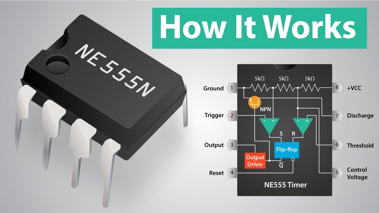
How a 555 Timer IC Works - YouTube

IC 555 Delay Timer circuit | on off delay circuit - Electroinvention

Explain the functional block diagram of Timer IC555

How does NE555 timer circuit work | Datasheet | Pinout | ElecCircuit.com

555 Timer IC-Block Diagram-Working-Pin Out Configuration-Data Sheet

Introduction to the 555 Timer - Circuit Basics

Introducing 555 Timer IC - Tutorial | Random Nerd Tutorials

timer ic 555 tester | Best Engineering Projects

GO LOOK IMPORTANTBOOK: IC 555 and CD 4047 measuring electronics